PCA9541D/03,112
Compare
PCA9541D/03,112
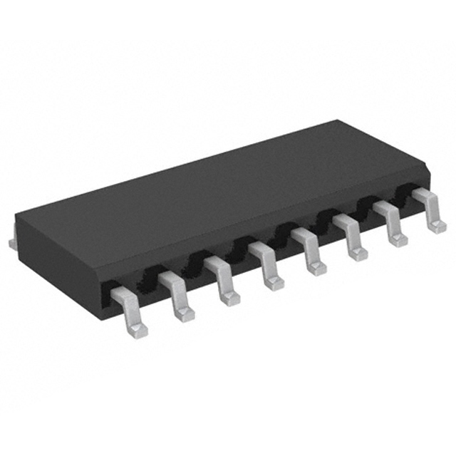
IC INTERFACE SPECIALIZED 16SO
Compare
Obsolete
Quantity Available:
4448
SZC Quality Assurance


NXP USA Inc.
NXP Semiconductors, a frontrunner in embedded controllers, offers a wide array of MCUs with Arm-based processors. Their innovation extends to robust Power Management for industry and automotive use. NXP's products globally empower and interconnect, fostering proficiency for individuals, organizations, and the world. Noteworthy is the integration of Freescale Semiconductor into NXP (December 2015).
View All Product from NXP USA Inc.


PCA9541D/03,112 1. General description
The PCA9541 is a 2-to-1 I2C-bus master selector designed for high reliability dual masterI2C-bus applications where system operation is required, even when one master fails orthe controller card is removed for maintenance. The two masters (for example, primaryand back-up) are located on separate I2C-buses that connect to the same downstreamI2C-bus slave devices. I2C-bus commands are sent by either I2C-bus master and are usedto select one master at a time. Either master at any time can gain control of the slavedevices if the other master is disabled or removed from the system. The failed master isisolated from the system and will not affect communication between the on-line masterand the slave devices on the downstream I2C-bus.Two versions are offered for different architectures. PCA9541/01 with channel 0 selectedat start-up and PCA9541/03 with no channel selected after start-up.The interrupt outputs are used to provide an indication of which master has control of thebus. One interrupt input (INT_IN) collects downstream information and propagates it tothe 2 upstream I2C-buses (INT0 and INT1) if enabled. INT0 and INT1 are also used to letthe previous bus master know that it is not in control of the bus anymore and to indicatethe completion of the bus recovery/initialization sequence. Those interrupts can bedisabled and will not generate an interrupt if the masking option is set.A bus recovery/initialization if enabled sends nine clock pulses, a not acknowledge, and aSTOP condition in order to set the downstream I2C-bus devices to an initialized statebefore actually switching the channel to the selected master.An interrupt is sent to the upstream channel when the recovery/initialization procedure iscompleted.An internal bus sensor senses the downstream I2C-bus traffic and generates an interruptif a channel switch occurs during a non-idle bus condition. This function is enabled whenthe PCA9541 recovery/initialization is not used. The interrupt signal informs the masterthat an external I2C-bus recovery/initialization needs to be performed. It can be disabledand an interrupt will not be generated.The pass gates of the switches are constructed such that the VDD pin can be used to limitthe maximum high voltage, which will be passed by the PCA9541. This allows the use ofdifferent bus voltages on each pair, so that 1.8 V, 2.5 V, or 3.3 V devices can communicatewith 5 V devices without any additional protection.The PCA9541 does not isolate the capacitive loading on either side of the device, so thedesigner must take into account all trace and device capacitances on both sides of thedevice, and pull-up resistors must be used on all channels.External pull-up resistors pull the bus to the desired voltage level for each channel. All I/Opins are 6.0 V tolerant.
PCA9541D/03,112 2. Features and benefits
2-to-1 bidirectional master selector I2C-bus interface logic; compatible with SMBus standards PCA9541/01 powers up with Channel 0 selected PCA9541/03 powers up with no channel selected and either master can take control ofthe bus Active LOW interrupt input 2 active LOW interrupt outputs Active LOW reset input 4 address pins allowing up to 16 devices on the I2C-bus Channel selection via I2C-bus Bus initialization/recovery function Bus traffic sensor Low Ron switches Allows voltage level translation between 1.8 V, 2.5 V, 3.3 V and 5 V buses No glitch on power-up Supports hot insertion Software identical for both masters Low standby current Operating power supply voltage range of 2.3 V to 5.5 V 6.0 V tolerant inputs 0 Hz to 400 kHz clock frequency ESD protection exceeds 2000 V HBM per JESD22-A114, 200 V MM perJESD22-A115, and 1000 V CDM per JESD22-C101 Latch-up testing is done to JEDEC Standard JESD78 which exceeds 100 mA Packages offered: SO16, TSSOP16, HVQFN16
PCA9541D/03,112 3. Applications
High reliability systems with dual masters Gatekeeper multiplexer on long single bus Bus initialization/recovery for slave devices without hardware reset Allows masters without arbitration logic to share resources
Product Attributes
| TYPE | DESCRIPTION | Select all |
|---|---|---|
| Package | Tube | |
| Series | - | |
| Mounting Type | Surface Mount | |
| Supplier Device Package | 16-SO | |
| Package / Case | 16-SOIC (0.154", 3.90mm Width) | |
| Voltage - Supply | 2.3V ~ 5.5V | |
| Interface | I²C, SMBus | |
| Applications | 2-Channel I²C Multiplexer | |
| Product Status | Obsolete |
Obsolete
Quantity Available:
4448
SZC Quality Assurance
NXP USA Inc.
NXP Semiconductors, a frontrunner in embedded controllers, offers a wide array of MCUs with Arm-based processors. Their innovation extends to robust Power Management for industry and automotive use. NXP's products globally empower and interconnect, fostering proficiency for individuals, organizations, and the world. Noteworthy is the integration of Freescale Semiconductor into NXP (December 2015).
View All Product from NXP USA Inc.You May Also Be Interested In
More Electronic Parts More
MCZ33903BS3EK
SYSTEM BASIS CHIP, POWER MANAGEM

MCZ33972AEKR2
INTERFACE CIRCUIT, PDSO32

MCZ33972EWR2
INTERFACE CIRCUIT, PDSO32

MCZ33904C3EKR2
SYSTEM BASIS CHIP, POWER MANAGEM

MCZ33904C5EK
SYSTEM BASIS CHIP, 2X 5.0 V/400M

MCZ33903C3EK
SYSTEM BASIS CHIP, 2X 3.3 V/400M
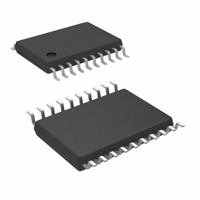
PCA9545APW,112
IC INTERFACE SPECIALIZED 20TSSOP
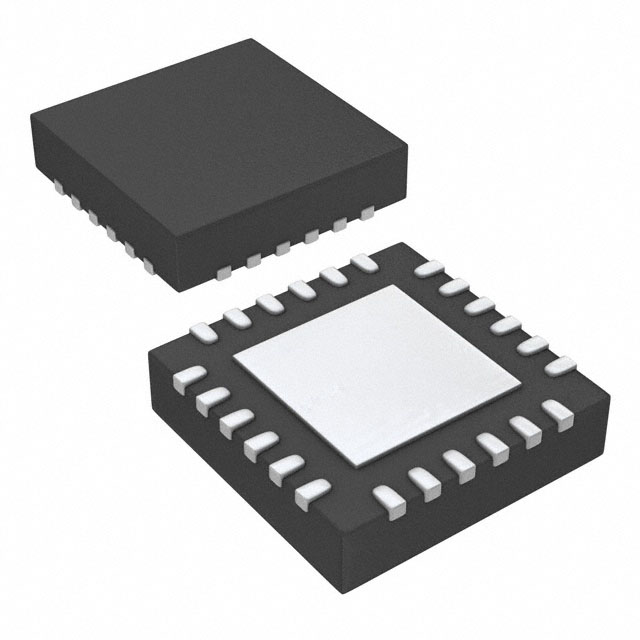
PCA9547BS,118
IC INTFACE SPECIALIZED 24HVQFN
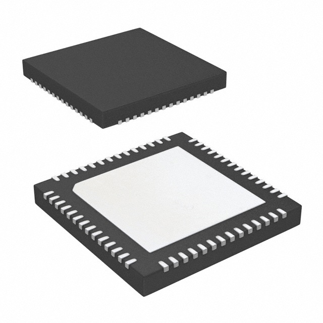
PTN3460IBS/F2MP
IC INTFACE SPECIALIZED 56HVQFN
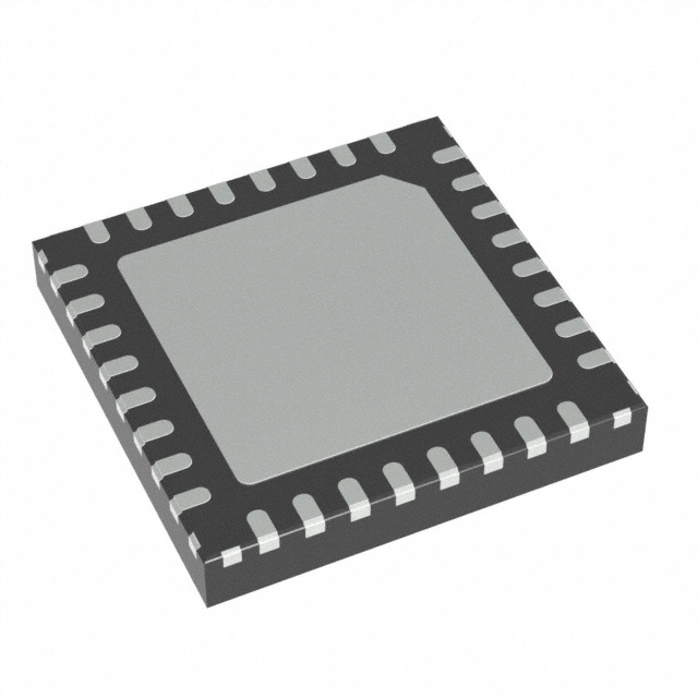
MC34978AES
IC INTERFACE SPECIALIZED 32QFN
45
Serves customers in 45 countries
1000+
Worldwide Manufacturers
$140M
$140M Growth in 5 Years
50.0M+
50M Parts Shipped in 5 Years