5962-9958302QPA
Compare
5962-9958302QPA
PWM CONTROLLER WITH WIDE INPUT R
Compare
Active
Quantity Available:
3193
SZC Quality Assurance


Texas Instruments
Texas Instruments Incorporated (TI) is a global semiconductor powerhouse, crafts advanced analog ICs and embedded processors. Fueled by top-tier minds, TI's innovations drive tech's future, impacting 100,000+ clients.
View All Product from Texas Instruments


5962-9958302QPA description
The TL5001 and TL5001A incorporate on a singlemonolithic chip all the functions required for apulse-width-modulation (PWM) control circuit. De-thesigned primarilyTL5001/A contains an error amplifier, a regulator, anoscillator, a PWM comparator with a dead-time-con-trollockout(UVLO), short-circuit protection (SCP), and an open-collector output transistor. The TL5001A has a typicalreference voltage tolerance of ±3% compared to ±5% for the TL5001.for power-supply control,undervoltageinput,The error-amplifier common-mode voltage ranges from 0 V to 1.5 V. The noninverting input of the error amplifieris connected to a 1-V reference. Dead-time control (DTC) can be set to provide 0% to 100% dead time by connectingan external resistor between DTC and GND. The oscillator frequency is set by terminating RT with an externalresistor to GND. During low VCC conditions, the UVLO circuit turns the output off until VCC recovers to its normaloperating range.The TL5001C and TL5001AC are characterized for operation from – 20°C to 85°C. The TL5001I and TL5001AI arecharacterized for operation from – 40°C to 85°C. The TL5001Q and TL5001AQ are characterized for operation from– 40°C to 125°C. The TL5001M and TL5001AM are characterized for operation from – 55°C to 125°C.
5962-9958302QPA detailed description
voltage referenceA 2.5-V regulator operating from VCC is used to power the internal circuitry of the TL5001 and TL5001A and as areference for the error amplifier and SCP circuits. A resistive divider provides a 1-V reference for the error amplifiernoninverting input which typically is within 2% of nominal over the operating temperature range.error amplifierThe error amplifier compares a sample of the dc-to-dc converter output voltage to the 1-V reference and generatesan error signal for the PWM comparator. The dc-to-dc converter output voltage is set by selecting the error-amplifiergain (see Figure 1), using the following expression:VO = (1 + R1/R2) (1 V)Figure 1. Error-Amplifier Gain SettingThe error-amplifier output is brought out as COMP for use in compensating the dc-to-dc converter control loop forstability. Because the amplifier can only source 45 µA, the total dc load resistance should be 100 kΩ or more.oscillator/PWMThe oscillator frequency (fosc) can be set between 20 kHz and 500 kHz by connecting a resistor between RT andGND. Acceptable resistor values range from 15 kΩ to 250 kΩ. The oscillator frequency can be determined by usingthe graph shown in Figure 5.The oscillator output is a triangular wave with a minimum value of approximately 0.7 V and a maximum value ofapproximately 1.3 V. The PWM comparator compares the error-amplifier output voltage and the DTC input voltageto the triangular wave and turns the output transistor off whenever the triangular wave is greater than the lesser ofthe two inputs.dead-time control (DTC)DTC provides a means of limiting the output-switch duty cycle to a value less than 100 %, which is critical for boostand flyback converters. A current source generates a reference current (IDT) at DTC that is nominally equal to thecurrent at the oscillator timing terminal, RT. Connecting a resistor between DTC and GND generates a dead-timereference voltage (VDT), which the PWM/DTC comparator compares to the oscillator triangle wave as describedin the previous section. Nominally, the maximum duty cycle is 0 % when VDT is 0.7 V or less and 100 % when VDTis 1.3 V or greater. Because the triangle wave amplitude is a function of frequency and the source impedance ofRT is relatively high (1250 Ω), choosing RDT for a specific maximum duty cycle, D, is accomplished using thefollowing equation and the voltage limits for the frequency in question as found in Figure 11 (Voscmax and Voscminare the maximum and minimum oscillator levels):
Product Attributes
| TYPE | DESCRIPTION | Select all |
|---|---|---|
| Product Status | Active | |
| Clock Sync | No | |
| Synchronous Rectifier | No | |
| Frequency - Switching | 20kHz ~ 500kHz | |
| Voltage - Supply (Vcc/Vdd) | 3.6V ~ 40V | |
| Output Phases | 1 | |
| Supplier Device Package | 8-CDIP | |
| Number of Outputs | 1 | |
| Package / Case | 8-CDIP (0.300", 7.62mm) | |
| Topology | Boost, Buck, Flyback | |
| Mounting Type | Through Hole | |
| Output Configuration | Positive | |
| Operating Temperature | -55°C ~ 125°C (TA) | |
| Function | Step-Up, Step-Down, Step-Up/Step-Down | |
| Control Features | Dead Time Control, Frequency Control, Ramp, Soft Start | |
| Output Type | Transistor Driver | |
| Serial Interfaces | - | |
| Package | Tube | |
| Series | - | |
| Duty Cycle (Max) | 100% |
Active
Quantity Available:
3193
SZC Quality Assurance
Texas Instruments
Texas Instruments Incorporated (TI) is a global semiconductor powerhouse, crafts advanced analog ICs and embedded processors. Fueled by top-tier minds, TI's innovations drive tech's future, impacting 100,000+ clients.
View All Product from Texas InstrumentsYou May Also Be Interested In
More Electronic Parts More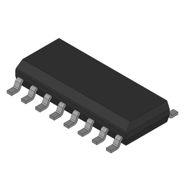
UC3844D
SWITCHING CONTROLLER
TL494CN
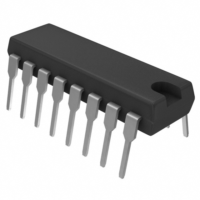
IC REG CTRLR BCK/PUSH-PULL 16DIP
TL494CD
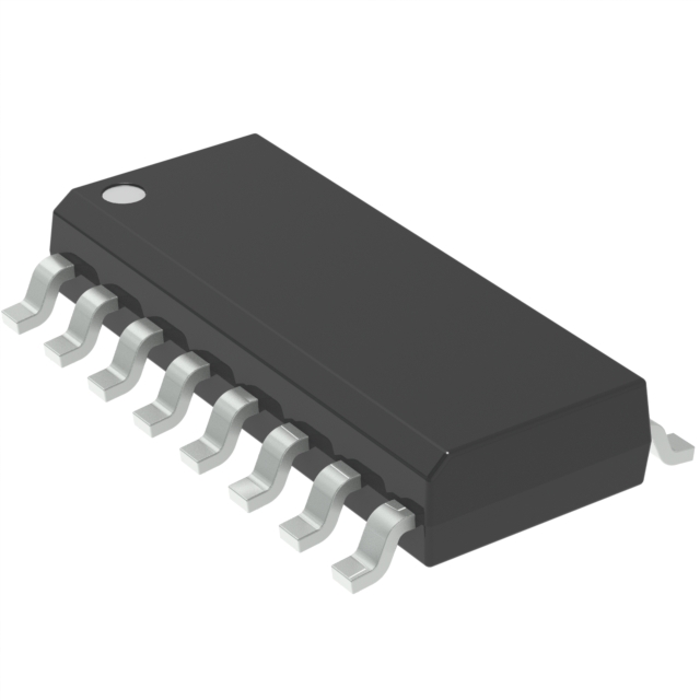
IC REG CTRLR BCK/PSH-PULL 16SOIC

SG2524N
IC REG CTRLR MULT TOPOLOGY 16DIP
SG3524D
IC REG CTRLR MULT TOP 16SOIC
UC2842AD
IC REG CTRLR PWM CM 14-SOIC
UC2845AD
IC REG CTRLR BUCK/BOOST 14SOIC
LTC3786EUD#TRPBF
IC REG CTRLR MULT TOPOLOGY 16QFN
LM3485MMX/NOPB
IC REG CTRLR BUCK 8VSSOP
TPS53219ARGTR
IC REG CTRLR BUCK 16QFN
45
Serves customers in 45 countries
1000+
Worldwide Manufacturers
$140M
$140M Growth in 5 Years
50.0M+
50M Parts Shipped in 5 Years