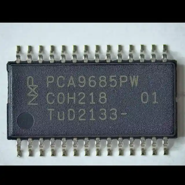
PCA9685PW,118
Compare
PCA9685PW,118
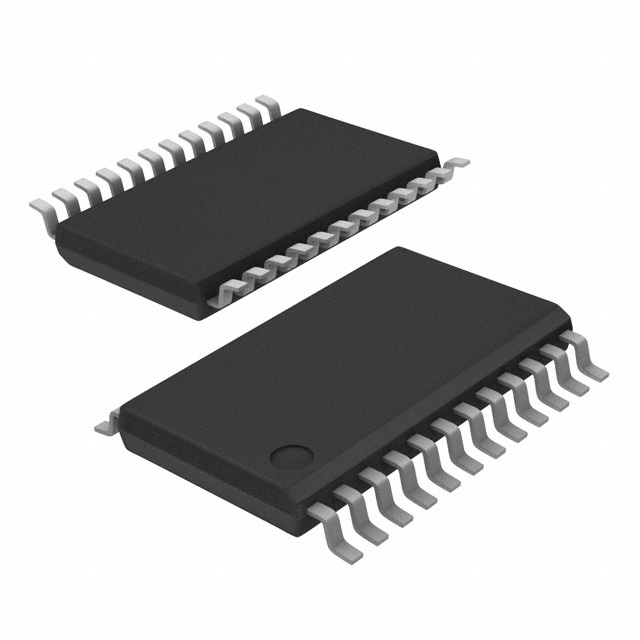
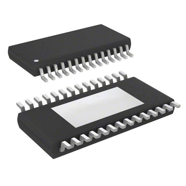
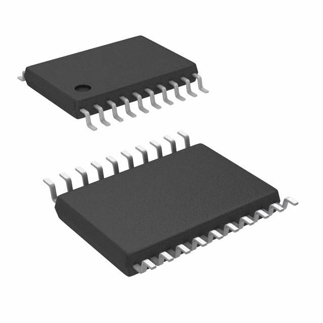
IC LED DRVR LIN PWM 25MA 28TSSOP


Compare
$1.66
Price update:a months ago
Available in stock:
10578


45
Serves customers in 45 countries
1000+
Worldwide Manufacturers
$140M
$140M Growth in 5 Years
50.0M+
50M Parts Shipped in 5 Years
NXP USA Inc.
NXP Semiconductors, a frontrunner in embedded controllers, offers a wide array of MCUs with Arm-based processors. Their innovation extends to robust Power Management for industry and automotive use. NXP's products globally empower and interconnect, fostering proficiency for individuals, organizations, and the world. Noteworthy is the integration of Freescale Semiconductor into NXP (December 2015).
View All Product from NXP USA Inc.


The PCA9685PW,118 is an I²C-bus controlled 16-channel LED controller optimized forRed/Green/Blue/Amber (RGBA) color backlighting applications. Each LED output has itsown 12-bit resolution (4096 steps) fixed frequency individual PWM controller that operatesat a programmable frequency from a typical of 24 Hz to 1526 Hz with a duty cycle that isadjustable from 0 % to 100 % to allow the LED to be set to a specific brightness value.All outputs are set to the same PWM frequency.
Each LED output can be off or on (no PWM control) or set at its individual PWM controllervalue. The LED output driver is programmed to be either open-drain with a 25 mA currentsink capability at 5 V or totem pole with a 25 mA sink, 10 mA source capability at 5 V. ThePCA9685PW,118 operates with a supply voltage range of 2.3 V to 5.5 V and the inputs andoutputs are 5.5 V tolerant. LEDs can be directly connected to the LED output (up to25 mA, 5.5 V) or controlled with external drivers and a minimum amount of discretecomponents for larger current or higher voltage LEDs.
The PCA9685PW,118 is in the new Fast-mode Plus (Fm+) family. Fm+ devices offer higherfrequency (up to 1 MHz) and more densely populated bus operation (up to 4000 pF).
Although the PCA9635 and PCA9685PW,118 have many similar features, the PCA9685PW,118 has features that make it more suitable for applications such as LCD or LEDbacklighting and Ambilight:
- The PCA9685PW,118 allows staggered LED output on and off times to minimize currentsurges. The on and off time delay is independently programmable for each of the16 channels. This feature is not available in PCA9635
- The PCA9685PW,118 has 4096 steps (12-bit PWM) of individual LED brightness control. ThePCA9635 has only 256 steps (8-bit PWM)
- When multiple LED controllers are incorporated in a system, the PWM pulse widthsbetween multiple devices may differ if PCA9635s are used. The PCA9685PW,118 has aprogrammable prescaler to adjust the PWM pulse widths of multiple devices
- The PCA9685PW,118 has an external clock input pin that will accept user-supplied clock(50 MHz max.) in place of the internal 25 MHz oscillators. This feature allowssynchronization of multiple devices. The PCA9635 does not have an external clock inputfeature
- Like the PCA9635, PCA9685PW,118 also has a built-in oscillator for the PWM control.However, the frequency used for PWM control in the PCA9685PW,118 is adjustable fromabout 24 Hz to 1526 Hz as compared to the typical 97.6 kHz frequency of thePCA9635. This allows the use of PCA9685PW,118 with external power supply controllers. Allbits are set at the same frequency
- The Power-On Reset (POR) default state of LEDn output pins is LOW in the case ofPCA9685. It is HIGH for PCA9635
The active LOW Output Enable input pin (OE) allows asynchronous control of the LEDoutputs and can be used to set all the outputs to a defined I²C-bus programmable logicstate. The OE can also be used to externally ‘pulse width modulate’ the outputs, which isuseful when multiple devices need to be dimmed or blinked together using softwarecontrol.
Software programmable LED All Call and three Sub Call I²C-bus addresses allow all ordefined groups of PCA9685PW,118 devices to respond to a common I²C-bus address, allowing,for example, all red LEDs to be turned on or off at the same time or marquee chasingeffect, thus minimizing I²C-bus commands. Six hardware address pins allow up to62 devices on the same bus.
The Software Reset (SWRST) General Call allows the master to perform a reset of thePCA9685PW,118 through the I²C-bus, identical to the Power-On Reset (POR) that initializes theregisters to their default state causing the outputs to be set LOW. This allows an easy andquick way to reconfigure all device registers to the same condition via software.
Feature
- 16 LED drivers. Each output programmable at:
- Off
- On
- Programmable LED brightness
- Programmable LED turn-on time to help reduce EMI
- 1 MHz Fast-mode Plus compatible I²C-bus interface with 30 mA high drive capabilityon SDA output for driving high capacitive buses
- 4096-step (12-bit) linear programmable brightness per LED output varying from fullyoff (default) to maximum brightness
- LED output frequency (all LEDs) typically varies from 24 Hz to 1526 Hz (Default of 1Ehin PRE_SCALE register results in a 200 Hz refresh rate with oscillator clock of25 MHz)
- Sixteen totem pole outputs (sink 25 mA and source 10 mA at 5 V) with softwareprogrammable open-drain LED outputs selection (default at totem pole). No inputfunction
- Output state change programmable on the Acknowledge or the STOP Command toupdate outputs byte-by-byte or all at the same time (default to ‘Change on STOP’)
- Active LOW Output Enable (OE) input pin. LEDs outputs programmable to logic 1,logic 0 (default at power-up) or ‘high-impedance’ when OE is HIGH
- 6 hardware address pins allow 62 PCA9685 devices to be connected to the sameI²C-bus
- Toggling OE allows for hardware LED blinking
- 4 software programmable I²C-bus addresses (one LED All Call address and three LEDSub Call addresses) allow groups of devices to be addressed at the same time in anycombination (for example, one register used for ‘All Call’ so that all the PCA9685s onthe I²C-bus can be addressed at the same time and the second register used for threedifferent addresses so that 1⁄3 of all devices on the bus can be addressed at the sametime in a group). Software enables and disables for these I²C-bus address
- Software Reset feature (SWRST General Call) allows the device to be reset throughthe I²C-bus
- 25 MHz typical internal oscillator requires no external components
- External 50 MHz (max.) clock input
- Internal power-on reset
- Noise filter on SDA/SCL inputs
- Edge rate control on outputs
- No output glitches on power-up
- Supports hot insertion
- Low standby current
- Operating power supply voltage range of 2.3 V to 5.5 V
- 5.5 V tolerant inputs
- -40 °C to +85 °C operation
- ESD protection exceeds 2000 V HBM per JESD22-A114, 200 V MM perJESD22-A115 and 1000 V CDM per JESD22-C101
- Latch-up testing is done to JEDEC Standard JESD78 which exceeds 100 mA
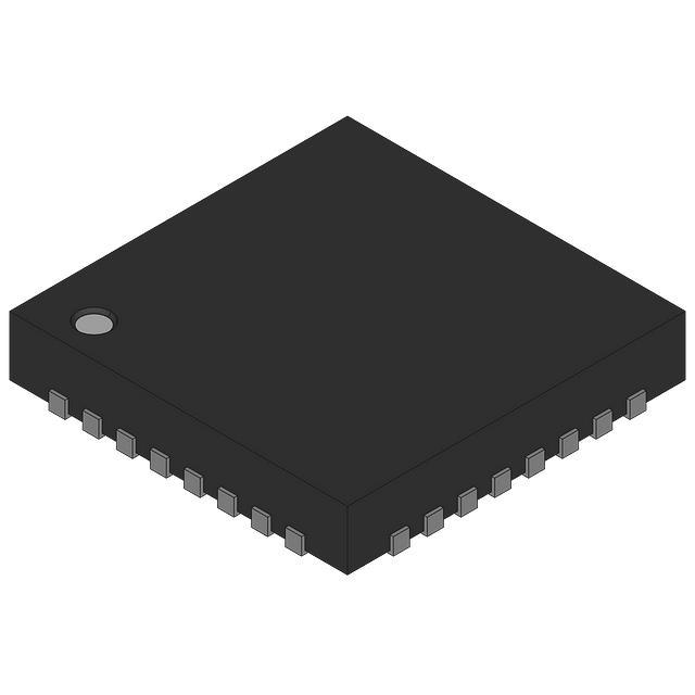
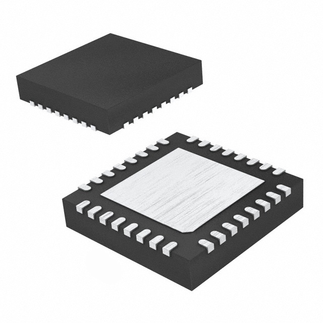
- Packages offered: TSSOP28, HVQFN28


Related Products
| Mfr Part # | Price ($) | Quantity Available | |
|---|---|---|---|
 PCA9655EDWR2GIC XPNDR 100KHZ I2C SMBUS 24SOIC | 4.84 |
2181
Marketplace | |
 PCA9685PW,112IC LED DRVR LIN PWM 25MA 28TSSOP | 1.52 |
2278
Marketplace | |
 PCA9655EMTTXGIC XPNDR 100KHZ I2C SMBUS 24QFN | 2.07 |
13088
Marketplace | |
 PCA9685BS,118IC LED DRVR LIN PWM 25MA 28HVQFN | 2.70 |
1099
Marketplace |
Product Attributes
| TYPE | DESCRIPTION | Select all |
|---|---|---|
| Current - Output / Channel | 25mA | |
| Frequency | 100kHz ~ 1MHz | |
| Package | Tape & Reel (TR) | |
| Dimming | PWM | |
| Product Status | Active | |
| Applications | Backlight | |
| Type | Linear | |
| Operating Temperature | -40°C ~ 85°C (TA) | |
| Mounting Type | Surface Mount | |
| Internal Switch(s) | Yes | |
| Package / Case | 28-TSSOP (0.173", 4.40mm Width) | |
| Number of Outputs | 16 | |
| Supplier Device Package | 28-TSSOP | |
| Voltage - Supply (Min) | 2.3V | |
| Voltage - Supply (Max) | 5.5V | |
| Voltage - Output | 5.5V |
Blog


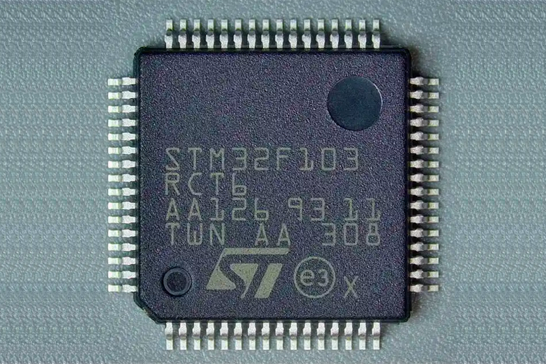 Unveiling the Future: The Surge of Microcontrollers in 2024In the dynamic world of electronic components, microcontrollers stand out as a testament to innovation and versatility. As we edge closer to 2024, the landscape for microcontrollers and semiconductors, spearheaded by giants like STMicroelectronics, Texas Instruments, and Microchip, is set for remarkable transformation.
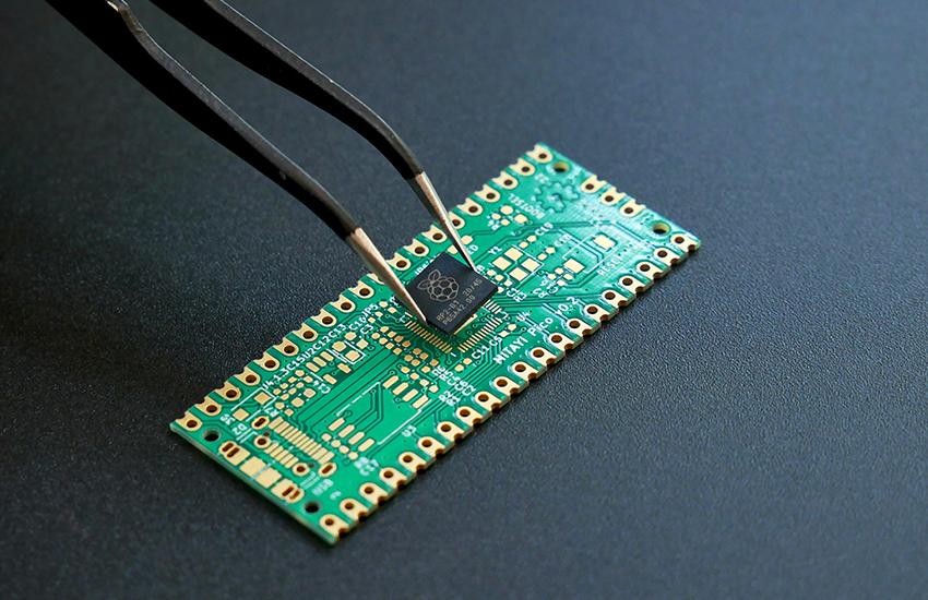 Microcontrollers vs. Microprocessors: Unveiling the Core Differences for Embedded Systems EngineeringSeasoned professionals in the realm of embedded systems engineering and product development within the electronics sphere often grapple with distinguishing between microcontrollers and microprocessors. Despite their foundational role in the design and fabrication of a myriad of electronic gadgets, understanding their unique functionalities based on mere definitions can be challenging:
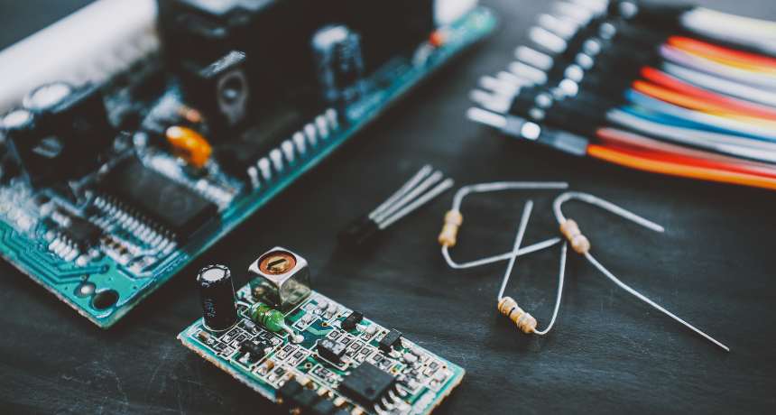 A Deep Dive into the Global Ceramic Capacitors MarketJoin us in exploring the emerging subplot of environmental consciousness within the global ceramic capacitors market.
 Mastering Current Measurement with MicrocontrollersUnlock precise current measurement secrets with Microcontrollers! Conquer challenges, meet superhero solutions, and revolutionize accuracy with on-chip Analog Core Independent Peripherals (CIPs).
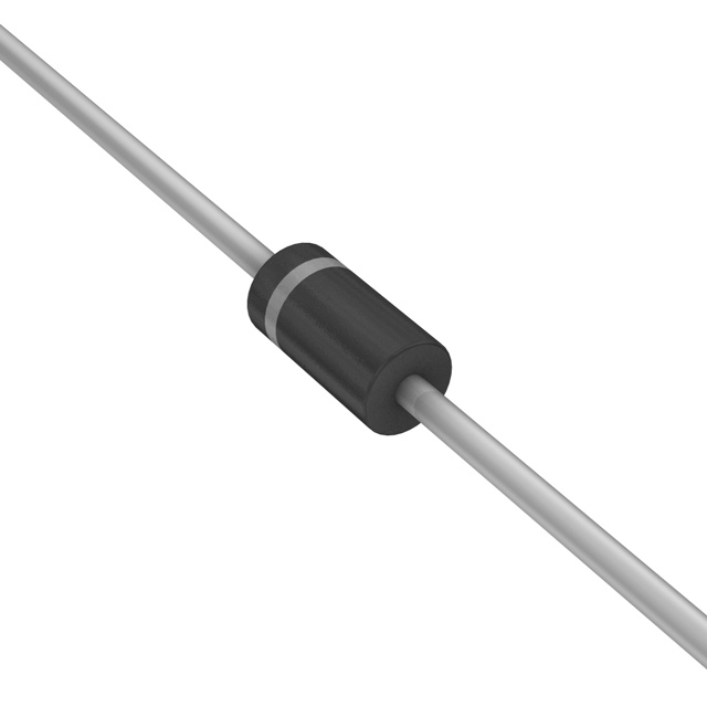 What is a Rectifier Diode: A Guide to BeginnersMeet the unsung heroes of electronics—Rectifier Diodes! Explore their magic, applications, and join the behind-the-scenes adventure into gadget power.

$1.66
Price update:a months ago
Available in stock:
10578
NXP USA Inc.
NXP Semiconductors, a frontrunner in embedded controllers, offers a wide array of MCUs with Arm-based processors. Their innovation extends to robust Power Management for industry and automotive use. NXP's products globally empower and interconnect, fostering proficiency for individuals, organizations, and the world. Noteworthy is the integration of Freescale Semiconductor into NXP (December 2015).
View All Product from NXP USA Inc.Blog
- Unveiling the Future: The Surge of Microcontrollers in 2024In the dynamic world of electronic components, microcontrollers stand out as a testament to innovation and versatility. As we edge closer to 2024, the landscape for microcontrollers and semiconductors, spearheaded by giants like STMicroelectronics, Texas Instruments, and Microchip, is set for remarkable transformation.
- Microcontrollers vs. Microprocessors: Unveiling the Core Differences for Embedded Systems EngineeringSeasoned professionals in the realm of embedded systems engineering and product development within the electronics sphere often grapple with distinguishing between microcontrollers and microprocessors. Despite their foundational role in the design and fabrication of a myriad of electronic gadgets, understanding their unique functionalities based on mere definitions can be challenging:
- A Deep Dive into the Global Ceramic Capacitors MarketJoin us in exploring the emerging subplot of environmental consciousness within the global ceramic capacitors market.
- Mastering Current Measurement with MicrocontrollersUnlock precise current measurement secrets with Microcontrollers! Conquer challenges, meet superhero solutions, and revolutionize accuracy with on-chip Analog Core Independent Peripherals (CIPs).
- What is a Rectifier Diode: A Guide to BeginnersMeet the unsung heroes of electronics—Rectifier Diodes! Explore their magic, applications, and join the behind-the-scenes adventure into gadget power.
Popular Manufacturers
View all manufactures More


Popular Parts Number
More Electronic Parts MorePCA9685PW,118
IC LED DRVR LIN PWM 25MA 28TSSOP
MC34844EPR2
IC LED DRVR RGLTR PWM 50MA 32QFN
PCA9532PW,112
IC LED DRVR PS I2C 25MA 24TSSOP
HEF4894BT/C118
LED DRIVER, 12-SEGMENT
PCA9952TW/Q900,118
IC LED DRV LIN PWM 57MA 28HTSSOP

PCA9550DP,118
IC LED DRVR LIN I2C 25MA 8TSSOP
ASL2500SHNY
IC LED DRIVER RGLTR NO 32HVQFN
HEF4894BTT-Q100118
LED DRIVER, 12-SEGMENT TSSOP20
PCA9633DP1,118
IC LED DRIVER PS PWM 25MA 8TSSOP
PCA9634PW,118
IC LED DRVR PS I2C 25MA 20TSSOP